LCD Alphanumeric Display - 2020
LCD Module Library Code
LCD Alphanumeric Display
PIC18F45k50 LCD Alphanumeric Display Interface
These types of display generally come with a HD44780 controller that has two operating modes 4-bit and 8-bit modes. There are usually 4 control lines and 8 data lines that are connected to a controller in this case a PIC microcontroller. The four control lines are defining how the data lines should be interpreted. The control pins are labelled EN – Enable Signal, RS – Register Select Signal, RW – Read/Write signal. To initialize an LCD the microcontroller needs to be able to send commands to the display. This is a simple function that sets the control lines and the 8-bit command to the LCD.
| Pin | Name | Description |
|---|---|---|
| RS | Register Select Signal | High signal - the data lines are interpreted as Command. Low signal - the data lines are interpreted as Data. |
| RW | Read or Write Signal | High signal - read operation mode.
Low signal - write operation mode. |
| EN | Enable Signal | Low - LCD module disabled. High - LCD module in operation mode. Pulse high to low - the LCD interprets the command or data. |
| D0 ~ D7 | Data/Command bits | 4 Bit mode – only D0~D3 are used. 8 bit mode – All D0 ~ D7 are used. |
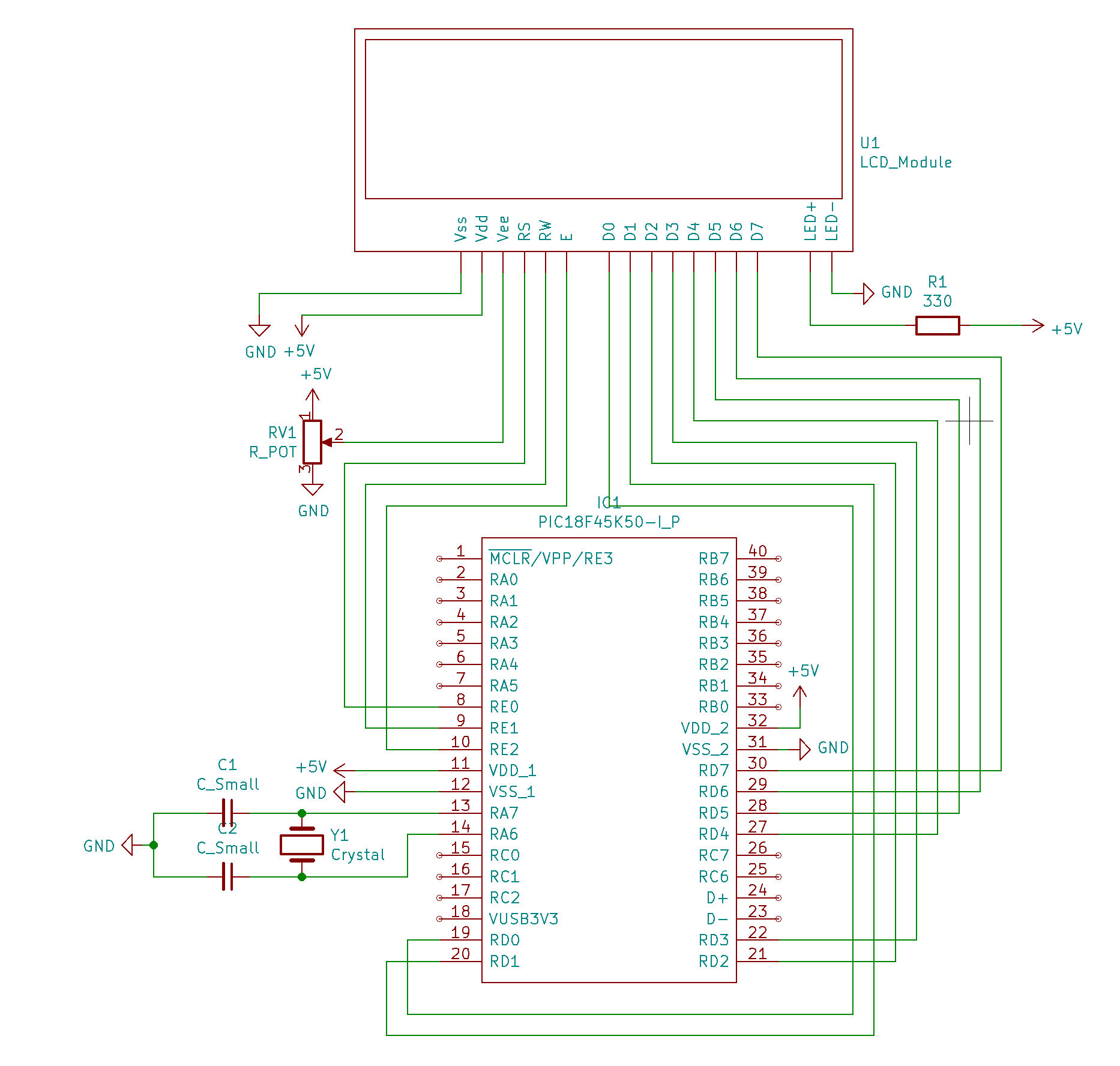
Circuit Diagram
Sending a commands
Place the byte command on the PORTD register, set RS to high for command, set RW to low for write mode, then pulse E high to low to signal the command. The LCD module will interpret the data bits as a command.
The LCD module will take the 8 data bits from the microcontroller as a write command when the enable signal pulses.
Sending a data
Sending data such as characters to the display is the exact same method as command expect that the RS signal is high. By placing the data on the PORTD register then set RS high (for data) and RW low for write command, then finally pulse the Enable signal will trigger the LCD to interpret the data bits as incoming data.
Waiting for LCD module
When sending either a command or data to the LCD module the program must wait for the LCD to process the command or data. This can be done by using a delay between the Enable signal pulse which has to be long enough for the LCD to process the instruction. I generally use a delay of 10ms between and after the enable pulse which seems to work fine.
LCD Commands
| Instruction | Value | Description |
|---|---|---|
| FIRST_LINE | 0x80 | Moves the cursor to the first line first character. |
| SECOND_LINE | 0xC0 | Moves the cursor to the second line first character. |
| THRID_LINE | 0x94 | Moves the cursor to the third line first character. |
| FOUR_LINE | 0xD4 | Moves the cursor to the four-line first character. |
| CURSOR_HOME | 0x02 | Moves the cursor back to the first line and character. |
| CURSOR_LEFT | 0x10 | Moves the cursor Left by one character. |
| CURSOR_RIGHT | 0x14 | Moves the Cursor Right by one character. |
| CURSOR_ON_BLINK_OFF | 0x0E | Disables the cursor from blinking but displays a solid cursor. |
| CURSOR_ON_BLINK_ON | 0x0F | Enables cursor and blinking of cursor. |
| CGRAM_WRITE | 0x40 | Enter RAM write mode, for custom characters. |
Initializing LCD Module
A sequence of command must be sent to the LCD module to initialize the start-up procedure. The first command to initialize the module is to set the operating mode of the display, in this case 8-bit mode.
Source Code
                                        /*
    * File: LCD Module
    * Author:  Mr Steven J Baldwin
    * Comments:
    * Revision history:
    */

    // This is a guard condition so that contents of this file are not included
    // more than once.
    #ifndef LCD_MODULE_H
    #define LCD_MODULE_H

    #define _XTAL_FREQ 20000000  //Crystal Frequency, used in delay

    #include <xc.h>

    //#define LCD_4BIT_MODE

    #define LCD_DATA   LATD
    #define LCD_EN     LATEbits.LATE2
    #define LCD_RW     LATEbits.LATE1
    #define LCD_RS     LATEbits.LATE0

    #define FIRST_LINE      0x80
    #define SECOND_LINE     0xC0
    #define THRID_LINE      0x94
    #define FOUR_LINE       0xD4

    #define CURSOR_HOME     0x02
    #define CURSOR_LEFT     0x10
    #define CURSOR_RIGHT    0x14

    #define CURSOR_ON_BLINK_OFF     0x0E
    #define CURSOR_ON_BLINK_ON      0x0F
    #define CURSOR_OFF              0x0C

    #define CGRAM_WRITE             0x40

    //
    // Custom Characters Data Send Values.
    //

    #define CUSTOM_CHAR_ONE             0x00
    #define CUSTOM_CHAR_TWO             0x01
    #define CUSTOM_CHAR_THREE           0x02
    #define CUSTOM_CHAR_FOUR            0x03
    #define CUSTOM_CHAR_FIVE            0x04


    //
    // initialize LCD module using 8 Bit
    //

    void lcd_init(void);

    //
    // Resset LCD
    //

    void lcd_reset(void);

    //
    // Send Command Instruction to LCD module
    //

    void lcd_send_cmd(unsigned char cmd);

    //
    // Send data to LCD Module
    //

    void lcd_send_data(unsigned char data);

    //
    // Send String to LCD Module
    //

    void lcd_send_string(const char* str);

    //
    // move cursor
    //

    void lcd_move_cursor(unsigned int x, unsigned int y);

    //
    // Clear LCD Display
    //

    void lcd_clear(void);


    //
    // Move cursor left by one
    //

    void lcd_cursor_left(void);

    //
    // Move cursor right by one
    //

    void lcd_cursor_right(void);

    //
    // shift display right
    //

    void lcd_shift_right(void);

    //
    // shift display left
    //

    void lcd_shift_left(void);


    #endif	/* XC_HEADER_TEMPLATE_H */
                                        /*
    * File: LCD Module
    * Author:  Mr Steven J Baldwin
    *
    */

    #include "lcd_module.h"

    void lcd_init(void)
    {
    #ifdef LCD_4BIT_MODE

        __delay_ms(100);              // Wait for LCD

        lcd_send_cmd(0x33);           // Function Set

        __delay_ms(45);               // Wait for LCD

        lcd_send_cmd(0x32);           // Function Set

        __delay_ms(45);               // Wait for LCD

        lcd_send_cmd(0x28);           // 4 bit mode (binary : 0010 1000)

        __delay_ms(45);               // Wait for LCD

        lcd_send_cmd(0x0E);           // Set Entry mode  (binary : 0000 1110)

        __delay_ms(45);               // Wait for LCD

        lcd_send_cmd(0x0C);           // Display On, Cursor Off, Blinking Off  (binary : 0000 1100)

        lcd_send_cmd(0x0E);           // Cursor On


    #else

        __delay_ms(100);            // Wait for LCD

        lcd_send_cmd(0x38);         // Function Set, 8-bit mode

        __delay_ms(15);             // Wait for LCD

        lcd_send_cmd(0x38);         // Function Set

        __delay_ms(15);             // Wait for LCD

        lcd_send_cmd(0x38);         //  Function Set

        __delay_ms(15);             // Wait for LCD

        lcd_send_cmd(0x06);         // Increment Cursor

        lcd_send_cmd(0x0E);         // Set Entry mode Cursor On, non blinking

        __delay_ms(15);             // Wait for LCD
    #endif
    }


    //
    // Send Command Instruction to LCD module
    //

    void lcd_send_cmd(unsigned char cmd)
    {
    #ifdef LCD_4BIT_MODE
        unsigned char buffer;

        //
        // Split cmd into two sets of 4 bits
        //

        LCD_RS = 0;           // set register select signal to instruction
        LCD_RW = 0;           // Set Read/Write pin to Write

        //
        // Send High nibblet to LCD Module
        //

        buffer = cmd;
        buffer &= 0xF0;         // Mask Lower Bits (set lower bits to zero)
        LCD_DATA &= 0x0F;       // Only work with high nibblet
        LCD_DATA |= buffer;     // Send High nibblet to LCD module

        LCD_EN = 1;             // Set Enable Signal Flag
        __delay_ms(1);          // give time for the LCD to respond to request
        LCD_EN = 0;             // Set Enable Signal Flag
        __delay_ms(1);          // give time for the LCD to respond to request

        //
        // Send Lower nibblet to LCD Module
        //

        buffer = cmd << 4;      // Move lower nibblet to higher nibblet (shift left fgour times)
        buffer &= 0xF0;         // Mask upper bits.
        LCD_DATA &= 0x0F;       // Mask lower bits.
        LCD_DATA |= buffer;

        LCD_EN = 1;             // Set Enable Signal Flag
        __delay_ms(1);          // give time for the LCD to respond to request
        LCD_EN = 0;             // Set Enable Signal Flag
        __delay_ms(1);          // give time for the LCD to respond to request

    #else
        LCD_DATA = cmd;       // Data to send to module via PORTD.
        LCD_RS = 0;           // set register select signal to instruction
        LCD_RW = 0;           // Set Read/Write pin to Write
        LCD_EN = 1;           // Set Enable Signal Flag

        __delay_ms(20);       // give time for the LCD to respond to request

        LCD_EN = 0;           // Set Enable Signal Flag to false

        __delay_ms(20);       // give time for the LCD to respond to request
    #endif
    }

    //
    // Send data to LCD Module
    //

    void lcd_send_data(unsigned char data)
    {
    #ifdef LCD_4BIT_MODE

        unsigned char buffer;
        LCD_RS = 1;           // set register select signal to instruction
        LCD_RW = 0;           // Set Read/Write pin to Write

        //
        // Send High nibblet to LCD Module
        //

        buffer = data;
        buffer &= 0xF0;           // Mask Lower Bits (set lower bits to zero)
        LCD_DATA &= 0x0F;         // Only work with high nibblet
        LCD_DATA |= buffer;       // Send High nibblet to LCD module

        LCD_EN = 1;               // Set Enable Signal Flag
        __delay_ms(1);            // give time for the LCD to respond to request
        LCD_EN = 0;               // Set Enable Signal Flag
        __delay_ms(1);            // give time for the LCD to respond to request

        //
        // Send Lower nibblet to LCD Module
        //

        buffer = data << 4;      // Move lower nibblet to higher nibblet (shift left fgour times)
        buffer &= 0xF0;          // Mask lower bits.
        LCD_DATA &= 0x0F;        //
        LCD_DATA |= buffer;

        LCD_EN = 1;              // Set Enable Signal Flag
        __delay_ms(1);           // give time for the LCD to respond to request
        LCD_EN = 0;              // Set Enable Signal Flag
        __delay_ms(1);           // give time for the LCD to respond to request

    #else
        LCD_RS = 1;           // set register select signal to instruction
        LCD_DATA = data;       // Data to send to module via PORTD.
        LCD_RW = 0;           // Set Read/Write pin to Write
        LCD_EN = 1;           // Set Enable Signal Flag

        __delay_ms(20);          // give time for the LCD to respond to request

        LCD_EN = 0;           // Set Enable Signal Flag to false

        __delay_ms(20);          // give time for the LCD to respond to request

        LCD_EN = 1;           // Set Enable Signal Flag to false

    #endif
    }


    //
    // Send String to LCD Module
    //

    void lcd_send_string(const char* str)
    {
        // loop trough each character in string
        while(*str)
        {
            //  Send Character data to LCD
            lcd_send_data(*str++);
        }
    }


    //
    // move cursor to given column and line number
    //

    void lcd_move_cursor(unsigned int x, unsigned int y)
    {
        if(y == 0)
        {
            lcd_send_cmd(FIRST_LINE + x);
        }else if(y == 1)
        {
            lcd_send_cmd(SECOND_LINE + x);
        }else if(y == 2)
        {
            lcd_send_cmd(THRID_LINE + x);
        }else if(y == 3)
        {
            lcd_send_cmd(FOUR_LINE + x);
        }
    }

    //
    // Clear LCD Display
    //

    void lcd_clear(void)
    {
        lcd_send_cmd(0x01);
    }


    //
    // Move Cursor Left by one character
    //

    void lcd_cursor_left(void)
    {
        lcd_send_cmd(CURSOR_LEFT);
    }

    //
    // Move Cursor Right by one character
    //

    void lcd_cursor_right(void)
    {
        lcd_send_cmd(0x14);
    }

    //
    // shift display right
    //

    void lcd_shift_right(void)
    {
        lcd_send_cmd(CURSOR_RIGHT);
    }

    //
    // shift display right
    //

    void lcd_shift_left(void)
    {
        lcd_send_cmd(CURSOR_LEFT);
    }

    //
    //  Clear and send string in one function
    //

    void lcd_update(const char* str){
        lcd_clear();
        lcd_send_string(str);
        __delay_ms(750);
    }
                                        /*
    * File:   main.c
    * Author: Mr Steven J Baldwin
    *
    * Created on 28 August 2020, 11:50
    */

    // CONFIG1L
    #pragma config PLLSEL = PLL4X   // PLL Selection (4x clock multiplier)
    #pragma config CFGPLLEN = OFF   // PLL Enable Configuration bit (PLL Disabled (firmware controlled))
    #pragma config CPUDIV = NOCLKDIV// CPU System Clock Postscaler (CPU uses system clock (no divide))
    #pragma config LS48MHZ = SYS24X4// Low Speed USB mode with 48 MHz system clock (System clock at 24 MHz, USB clock divider is set to 4)

    // CONFIG1H
    #pragma config FOSC = LP        // Oscillator Selection (LP oscillator)
    #pragma config PCLKEN = OFF     // Primary Oscillator Shutdown (Primary oscillator shutdown firmware controlled)
    #pragma config FCMEN = OFF      // Fail-Safe Clock Monitor (Fail-Safe Clock Monitor disabled)
    #pragma config IESO = OFF       // Internal/External Oscillator Switchover (Oscillator Switchover mode disabled)

    // CONFIG2L
    #pragma config nPWRTEN = ON     // Power-up Timer Enable (Power up timer enabled)
    #pragma config BOREN = OFF      // Brown-out Reset Enable (BOR disabled in hardware (SBOREN is ignored))
    #pragma config BORV = 285       // Brown-out Reset Voltage (BOR set to 2.85V nominal)
    #pragma config nLPBOR = ON      // Low-Power Brown-out Reset (Low-Power Brown-out Reset enabled)

    // CONFIG2H
    #pragma config WDTEN = OFF      // Watchdog Timer Enable bits (WDT disabled in hardware (SWDTEN ignored))
    #pragma config WDTPS = 1        // Watchdog Timer Postscaler (1:1)

    // CONFIG3H
    #pragma config CCP2MX = RB3     // CCP2 MUX bit (CCP2 input/output is multiplexed with RB3)
    #pragma config PBADEN = OFF     // PORTB A/D Enable bit (PORTB<5:0> pins are configured as digital I/O on Reset)
    #pragma config T3CMX = RB5      // Timer3 Clock Input MUX bit (T3CKI function is on RB5)
    #pragma config SDOMX = RC7      // SDO Output MUX bit (SDO function is on RC7)
    #pragma config MCLRE = OFF      // Master Clear Reset Pin Enable (RE3 input pin enabled; external MCLR disabled)

    // CONFIG4L
    #pragma config STVREN = OFF     // Stack Full/Underflow Reset (Stack full/underflow will not cause Reset)
    #pragma config LVP = OFF        // Single-Supply ICSP Enable bit (Single-Supply ICSP disabled)
    #pragma config ICPRT = OFF      // Dedicated In-Circuit Debug/Programming Port Enable (ICPORT disabled)
    #pragma config XINST = OFF      // Extended Instruction Set Enable bit (Instruction set extension and Indexed Addressing mode disabled)

    // CONFIG5L
    #pragma config CP0 = ON         // Block 0 Code Protect (Block 0 is code-protected)
    #pragma config CP1 = ON         // Block 1 Code Protect (Block 1 is code-protected)
    #pragma config CP2 = ON         // Block 2 Code Protect (Block 2 is code-protected)
    #pragma config CP3 = ON         // Block 3 Code Protect (Block 3 is code-protected)

    // CONFIG5H
    #pragma config CPB = ON         // Boot Block Code Protect (Boot block is code-protected)
    #pragma config CPD = ON         // Data EEPROM Code Protect (Data EEPROM is code-protected)

    // CONFIG6L
    #pragma config WRT0 = ON        // Block 0 Write Protect (Block 0 (0800-1FFFh) is write-protected)
    #pragma config WRT1 = ON        // Block 1 Write Protect (Block 1 (2000-3FFFh) is write-protected)
    #pragma config WRT2 = ON        // Block 2 Write Protect (Block 2 (04000-5FFFh) is write-protected)
    #pragma config WRT3 = ON        // Block 3 Write Protect (Block 3 (06000-7FFFh) is write-protected)

    // CONFIG6H
    #pragma config WRTC = ON        // Configuration Registers Write Protect (Configuration registers (300000-3000FFh) are write-protected)
    #pragma config WRTB = ON        // Boot Block Write Protect (Boot block (0000-7FFh) is write-protected)
    #pragma config WRTD = ON        // Data EEPROM Write Protect (Data EEPROM is write-protected)

    // CONFIG7L
    #pragma config EBTR0 = ON       // Block 0 Table Read Protect (Block 0 is protected from table reads executed in other blocks)
    #pragma config EBTR1 = ON       // Block 1 Table Read Protect (Block 1 is protected from table reads executed in other blocks)
    #pragma config EBTR2 = ON       // Block 2 Table Read Protect (Block 2 is protected from table reads executed in other blocks)
    #pragma config EBTR3 = ON       // Block 3 Table Read Protect (Block 3 is protected from table reads executed in other blocks)

    // CONFIG7H
    #pragma config EBTRB = ON       // Boot Block Table Read Protect (Boot block is protected from table reads executed in other blocks)

    // #pragma config statements should precede project file includes.
    // Use project enums instead of #define for ON and OFF.

    #include <xc.h>
    #include "lcd_module.h"

    //Crystal Frequency in herz (20Mhz) this macro used for the xc8 __delay functions.
    #define _XTAL_FREQ 20000000


    /**
    *
    *  Main program routine
    *
    */

    void main(void) {

        /*
        * ANSELx registers
        */

        ANSELD = 0x00;      //  Set as digital
        ANSELC = 0x00;      //  Set as digital
        ANSELB = 0x00;      //  Set as digital
        ANSELE = 0x00;      //  Set as digital
        ANSELA = 0x00;      //  Set as digital

        ADCON1 = 0x0F;      //  Disable all Analog Inputs

        TRISA = 0x00;       //  Set Port A as output
        TRISB = 0x00;       //  Set Port B as output
        TRISC = 0x00;       //  Set Port C as output
        TRISD = 0x00;       //  Set Port D as output
        TRISE = 0x00;       //  Set Port E as output

        LATA = 0x00;        //  Clear Port A
        LATB = 0x00;        //  Clear Port B
        LATC = 0x00;        //  Clear Port C
        LATD = 0x00;        //  Clear Port D
        LATE = 0x00;        //  Clear Port E

        //	Initialize LCD Module
        lcd_init();

        // Send String to Display
        lcd_send_string("Hello World.");

        __delay_ms(1000);               //  Wait 1 second

        //  Execution Loop
        while(1){
            __delay_ms(1000);           //  Wait 1 second
            lcd_clear();				//	Clear Display

            //	Display on first line
            lcd_send_string("First Line");

            //	Move to the second line
            lcd_move_cursor(0, 1);

            lcd_send_string("Second Line");

            //	Move to first line
            lcd_move_cursor(0, 0);
        }

        return;
    }